Liquid crystals are fluids that exhibit an ordered molecular structure. When heated, they may undergo a phase transition to a state in which this order is lost. Several types of liquid crystal materials exist, but this discussion focuses on nematic liquid crystals. In the ordered state, these fluids display crystalline behavior and birefringence. Nematic liquid crystal molecules are typically rod-like or thread-like in shape, which gives rise to the term “nematic.” In the liquid crystalline phase, the molecules tend to align with one another.
Liquid crystals typically have different permittivity (and index of refraction) values parallel and perpendicular to the molecular axis. As a result, their molecules tend to align parallel to an applied electric field.
Alignment Layer
When no electric field is applied, the direction at which the liquid crystal material aligns can be influenced by the texture or chemical properties of the layers adjacent to it. The alignment layer causes nearby molecules to align in a particular direction with respect to the surface, as shown in the upper figure of each pair of figures. Molecules throughout the rest of the liquid crystal material tend to align with their neighbors, so the orientation of the alignment layer influences the alignment of the entire liquid crystal layer.
For example, a homogeneous alignment (or planar alignment) may be achieved by roughening, sanding, or polishing the alignment layer in one direction.
A homeotropic alignment (or perpendicular alignment can be achieved by vapor deposition of SiOx (see United States Patent Application # 20050122456). If the SiOx is deposited at an oblique angle, the liquid crystal material will have a slight tilt. (See https://en.wikipedia.org/wiki/Alignment_layer, https://en.wikipedia.org/wiki/Homeotropic_alignment, and https://en.wikipedia.org/wiki/Homogenious_alignment).
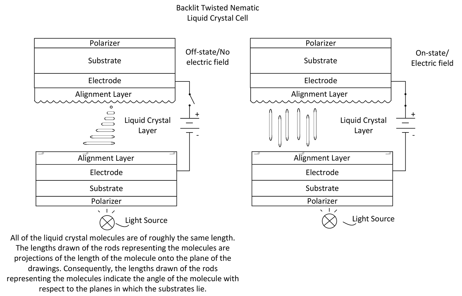 Twisted Nematic LCD Structure
LCDs are passive electro-optic devices that operate as electrical shutters. In the figures, a light source is included behind the display, forming a backlit LCD.
Twisted nematic LCDs typically have a sandwich-like structure, with the liquid crystal material positioned at the center. Each side may include a substrate that provides physical support for the surrounding layers. A polarizer is located on the exterior-facing side of each substrate, while an electrode and an alignment layer are placed on the interior side.
Electrochemical Properties of the LCD
The electrodes apply an electric field across the liquid crystal material.
In a twisted nematic LCD, the two alignment layers are oriented perpendicular to one another. This arrangement causes the liquid crystal material to twist by 90 degrees from one alignment layer to the other, as illustrated in the top drawing.
When an electric field is applied, the nematic liquid crystal molecules tend to align perpendicular to the alignment layers and parallel to the electric field, as illustrated in the bottom drawing.
Optical Properties
Linear Polarizers
Each linear polarizer allows linearly polarized light to pass when the light is polarized parallel to the polarizer’s transmission axis. When two ideal linear polarizers have parallel transmission axes, polarized light passes through both, and the pair appears transparent. When their transmission axes are perpendicular, the light is blocked, and the pair appears opaque. In practice, the opacity depends on the quality of the polarizers.
LCD Operation
As shown in the drawings, at least one alignment layer is oriented parallel to the transmission axis of the nearest polarizer. The liquid crystal material rotates the direction of polarization as the light follows the twist of the material. If the two polarizers are perpendicular, the LCD is transparent in the OFF state and opaque in the ON state. If the polarizers are parallel, the LCD is opaque in the OFF state and transparent in the ON state.
The LCD cells may include color filters or colored dyes.
Response Time
Twisted nematic LCDs can have response times as slow as 100 to 200 milliseconds, making them the slowest component in many systems. The response times can be improved by adding a chiral dopant or mixing a cholesteric liquid crystal material, so that when the electric field is removed, the liquid crystal material returns to its twisted state (improving the decay time). In at least the older literature, thicknesses of the liquid crystal material of 10 microns to 20 microns are popular. Presumably, using a thinner layer of liquid crystal material will also improve the response time (by improving the rise time). Using such techniques, some report twisted nematic liquid crystal display cells with response times of .5 milliseconds (which, although a significant improvement, is still relatively slow compared to other electrical components).
Transparent Electrodes
In the LCD patent literature, indium tin oxide electrodes are popular. However, other metals/metal oxides can be used, and transparent electrodes can be made in other ways from other materials. For example, some conductive materials, when thin enough, are transparent. For example, gold can be transparent at about 2-3 nanometers.
Voltage/Power Requirement
Twisted nematic LCD cells (and other field effect LCD cells) only require 1.5 to 2 volts to maintain the untwisted state (or other active state). Since no current is required for the twisted and untwisted states (or other transparent and opaque states), the power requirement for LCDs is low.
See the discussions at https://en.wikipedia.org/wiki/Twisted_nematic_field_effect and https://en.wikipedia.org/wiki/Liquid_crystal for more information.
DYNAMIC SCATTERING LCD
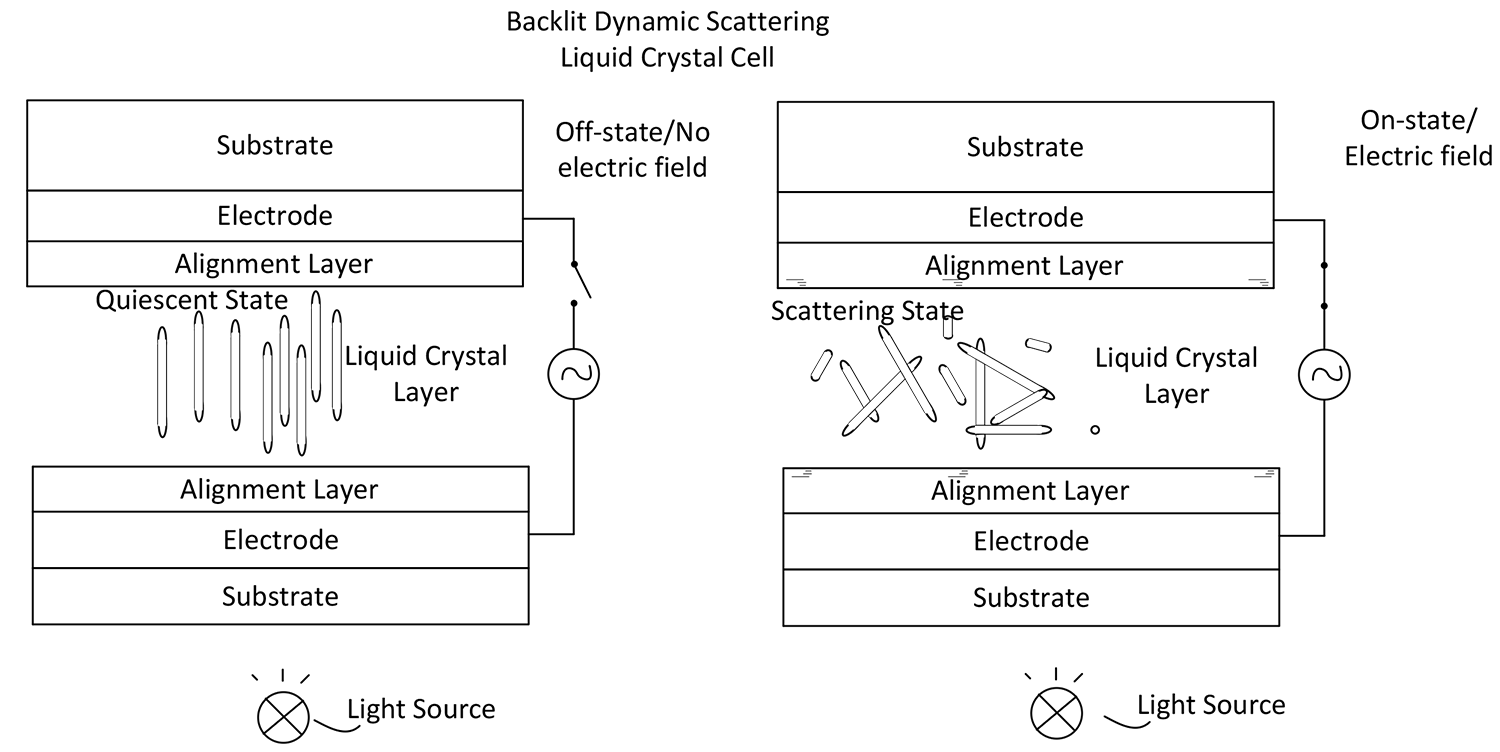
Dynamic scattering mode (DSM), in [the] literature also named electrohydrodynamic instabilities (EHDI), was first discovered in liquid crystals and reported in the 1960s. It was initially used to produce scattering-based monitors, with [the] following conditions being met to generate the DSM effect: (1) Liquid crystals (LC) demonstrate negative dielectric anisotropy. (2) Liquid crystals are initially homeotropically aligned (with a direction of being perpendicular to the substrate). (3) Charge carriers in the form of ions are in liquid crystals, therefore increasing the conductivity of the LC, reducing the threshold voltage and generating turbulent flow motion in LC (United States Patent Application 20210355384).
The effect of the current on the LCD during dynamic scattering is sometimes described as similar to pushing through a log jam floating on water. As one pushes through the logs, they change direction.
The ions push through the log jam and disrupt the array, creating comparatively large regions of turbulence (from one micron to five microns across). The turbulence causes the thin layer of nematic material, which was originally transparent, to become milky white because the turbulent fluid scatters light. This effect is called dynamic scattering. Dynamic scattering can be halted and the clarity of the liquid crystal restored simply by turning off the voltage (US patent # 4006968).
The effect can occur using both AC or DC currents. Activating the scattering state can require several kilovolts, but can also be as low as 25 volts, depending on the system. However, even 25 volts is significantly higher than the voltage needed for twisted nematic LCDs (or other field effect LCDs).
Logically, when applying an alternating current, as the direction of the electric field changes, the liquid crystal molecules change their direction. However, apparently, the response time of the liquid crystal molecules is too long to create a strong scattering effect from the alternating electric field alone.
Since no polarizers are needed, the display can be brighter than the twisted nematic LCD. The alignment layer is optional. The quiescent state will be transparent without the alignment layer. Nonetheless, the alignment layers could help keep the appearance of the transparent state more uniform and may help avoid some undesired birefringent effects. A perpendicular alignment may increase the transparency of the quiescent state. The contrast between a milky-white state and a clear state is not necessarily very high. Nonetheless, commercial versions of dynamic scattering LCDs can have a contrast as high as 15 to 1 or higher. Presumably, because of the higher voltage requirements and difficulties in obtaining a high contrast, dynamic scattering LCDs are, at best, not widely used commercially today, if at all.
David Lewis, Registered Patent Agent
408-993-1800
david@jlg-iplaw.com | LinkedIn